Psi-Value Determination (Ψ-Value Calculation)
The
Psi-Value Determination Form is used for automatic
calculation of the linear thermal transmittance Psi of the (linear) thermal heat bridge
(correction factors Psi (Ψ,
LΨ, ) for the currently analysed
two dimensional (2D)
building component according to the EN ISO 10211 (or EN ISO 10077).
Most typical 2D cases will be calculated without any additional user
intervention. The automation is supported by:
- calculation of the thermal coupling coefficient L2D (as calculated within by the steady state, two dimensional thermal heat bridge simulation),
- automatic identification of characteristic U-Values at adiabatic boundaries of the model (also shown within the Modelling Report) and
- determination of respective lengths (exterior- or interior based) resulting from the Reference Point which are determined automatically if possible.
Some limitations of that automation depend on the particular geometry and can be
controlled by the user.
Remark: Psi-Value Determination Form will show disabled if neither
automatic nor partly automatic determination is feasible for the particular
model. The message related to such situation will be displayed also. Manual arbitrary calculation of Psi-Value is then supported by the
Psi-Value Calculator tool only.
Remark: The model is interpreted as two dimensional if it is homogenous
in the Z direction (the grid contains only one layer in Z).
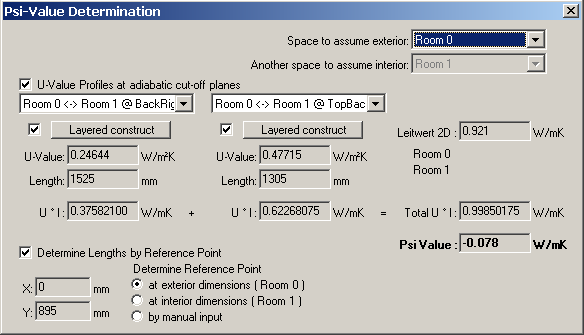
| Space to assume -Exterior -Interior |
Select the space name which is to be assumed exterior at
first. The choice of the value of the thermal coupling coefficient L2D, the
automatic determination of the Reference Point and
the selection of
characteristic U-Value Profiles at adiabatic
boundaries all depend on that input. By default AnTherm will pick the name of the first space (as sorted in alphabetic order) which in particular is assigned the lowest temperature during later evaluations. |
| Coupling Coefficient L2D | The thermal coupling coefficient specific to the component
under consideration (as calculated and reported within the
Coupling Coefficients
report,
for example). As soon as simulation results of a two dimension calculation are available or created within AnTherm the Psi-Value Determination Form will pick the value of the coupling coefficient between the two spaces (exterior and interior) automatically. The value transferred is the median of the two corresponding matrix elements divided by the thickness in Z (in 2D it is 1 meter) and rounded according to the close-up error. |
| U-Value Profiles at adiabatic cut-off planes | Turn that switch on to request AnTherm to pick the profiles
automatically at adiabatic boundaries. Available U-Value Profiles are then
shown in the two choice boxes displayed just below the switch for further
selection. If turned off you will have to provide U-Values manually (either
by the value input or as calculated with a U-Value
Calculator) By default AnTherm attempts to automatically find
appropriate profiles. |
| U-Value Profile selection | Characteristic profiles at adiabatic cut-off planes found
automatically are available for selection. Remark: AnTherm will offer only profiles connected to the exterior or interior spaces. The layered construct at the profile chosen is automatically created and passed to the respective U-Value Calculator in the fields shown below, thus replacing the earlier entries therein. By default AnTherm will automatically pick the first two orthogonal profiles from the list available. |
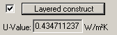
| Layered construct | The button provides the means of viewing (or entering) a
layered construct for the calculation of its characteristic U-Value. Remark: The layered construct editor (the U-Value Calculator) will block changes (editing buttons and menues will be grayed) if the construct is provided from the profiles identified by AnTherm. If you wish to override the construct by changing it you must uncheck the "U-Value Profiles at adiabatic cut-off planes" switch above. Remark: If specific U-Value is calculated from a layered construct entered within a U-Value calculator (or from the characteristic profile selected), the checkmark left to the button "Layered Construct" is marked checked. To override the U-Value manually uncheck the checkmark left to the button "Layered Construct". |
| U-Value | The U-Value specific the the components part concerned (as
calculated with a U-Value
Calculator, for example). Remark: If specific U-Value is provided by a layered construct entered within a U-Value calculator, the checkmark left to the button "Layered Construct" is marked checked and this field is marked read-only. To override the value manually uncheck the checkmark left to the button "Layered Construct". |
| Length | The length to be used for the respective U-Value above. Remark: If respective lengths are determined automatically from the Reference Point, the respective fields are shown read-only. |
| Determine Lengths by Reference Point | Lengths shall be determined from the specific
Reference
Point found automatically for exterior or interior dimensions or given by
manual entry. Remark: If respective lengths cannot be determined from any Reference Point that choice box and controls below it are shown disabled.. |
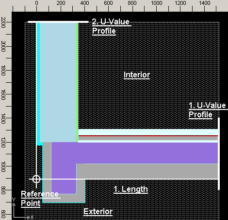
| Reference Point at -exterior -interior -manual |
The Reference Point shall be found automatically at
exterior or interior dimensions or specified by manual entry. Remark: If the respective reference point cannot be determined at some specific automation, that choices are shown disabled. See the explanation graphics below. |
| U * l | The result of the multiplication of respective values of U and l. |
| Total U * l | The sum of respective U * l multiplications. |
| Psi-Value (Ψ) | The resulting Psi-Value (Ψ, LΨ, ); the linear thermal transmittance |
Following picture describes the relations within the various objects used in that automated calculation:
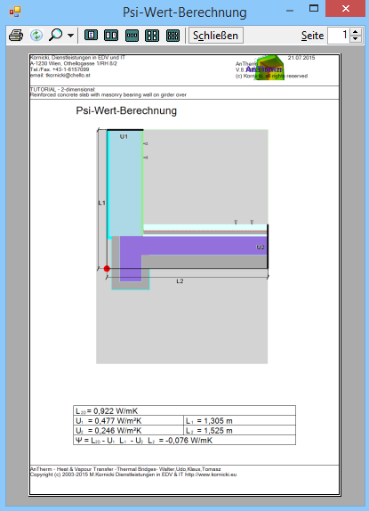
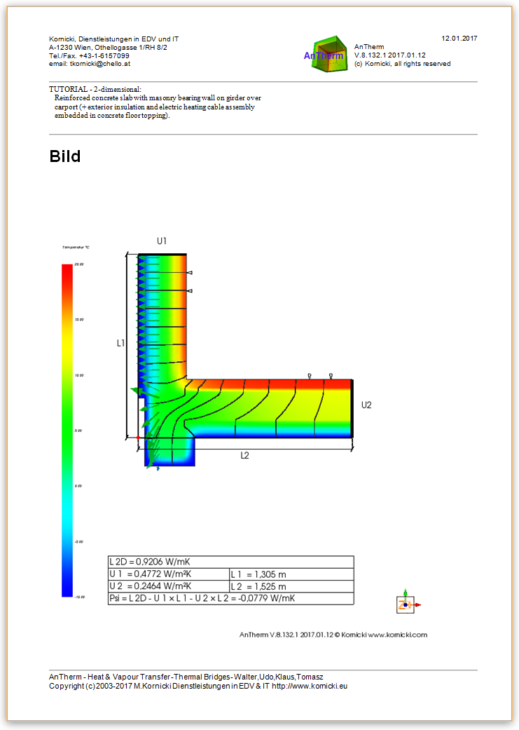
You can call the graphic for the Psi evaluation from the program or from the Result 3D window.
Note: The graphic can only be displayed if you use the automatically obtained U values and lengths. Otherwise this possibility is deactivated as it could lead to misinterpretations.
To call the graphic from the Result 3D window, do the following steps:
- Go to the Result 3D window.
- Click the tab "3D".
- Click the icon "Reset" (top left).
- Activate checkbox "Psi".
Calculating U-Values with U-Value Calculator
To
calculate respective U-Value with an integrated
U-Value Calculator, press
the button "Layered Construct", build or load the layered construct within the
U-Value Calculator which
is shown thereafter and confirm the calculated result by pressing the Ok-button
therein.
The calculated U-Value of a layered construct is shown in the U-Value field
which is then marked read-only. The checkmark left to the button "Layered
Construct" confirms, that the value shown is based on respective layered
construct.
The actual data of a layered construct can be changed at any time by pressing the button "Layered Construct" again and editing the data within the U-Value Calculator shown thereafter.
Remark: The actual data of a layered construct is retained until the
form is closed. To save the data of each respective layered construct use
the "Save" function within the
U-Value Calculator.
Remark: You can drag & drop any layered construct (as it is available
from a U-Value Calculator
if it is run separately) onto the one of U-Value / Length blocks in this window
also.
Remark: To override the value manually uncheck the checkmark left to
the button "Layered Construct".
Remark: If no data of a layered construct has been applied yet, the
checkmark left to the button "Layered Construct" is shown greyed.
Thermal Coupling Coefficient L2D obtained from AnTherm
AnTherm's "Coupling Coefficients Report" provides the matrix of thermal coupling coefficients resulting from steady state simulation of respective modelled construction. As AnTherm displays both, the interior and exterior calculated values for precision validation purposes, the mean value of both is used.
Important: U-Values and lengths used for the Psi-Value calculation must correspond to the thermal coupling coefficient of the modelled component in the manner defined within EN ISO 10211 and EN ISO 13789.
As soon as simulation results of a two dimension calculation are available or
created in AnTherm the Psi-Value Calculator will pick the value of the thermal coupling
coefficient between the two selected spaces automatically.
Remark: The model is interpreted as two dimensional if it is homogenous
in the Z direction (the grid contains only one layer in Z).
Remark: The value transferred is calculated as the mean value of the two
matrix elements which apply and divided y the thickness in the Z direction (in
2D it is 1 Meter) and then rounded according to the current close-up error.
U-Values obtained automatically by AnTherm
AnTherm's "Modelling Report" shows U-Values for all layered constructs at adiabatic cut-off planes of the modelled component.
Important: U-Values and lengths used for the Psi-Value calculation must correspond to the therml coupling coefficient of the modelled component in the manner defined within EN ISO 10211 and EN ISO 13789.
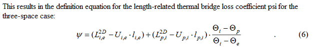
Psi Value Calculation in 3 Space Case and for Unheated Buffer Spaces
The following documents are in the German language.
Zur Berechnung von
Ψ-Werten für Baukonstruktionen im Bereich bodenberührter Bauteile
Zur Berechnung von
Ψ-Werten im 3-Raum-Fall; Spezialfall: unbeheizte Pufferräume
See also: Coupling Coefficients and Precision report, Modelling report, Psi-Value Calculator (Tool), U-Value Calculator (Tool), Project types, Linear and Point Transmittance, On calculation of Ψ-values for building constructions in connection with ground, EN ISO 14683, EN ISO 13789